What is reverse osmosis article is aiming towards people that has little or no experience with Reverse Osmosis water and will attempt to explain the basics in simple terms that should leave the reader with a better overall understanding of Reverse Osmosis water technology and its applications.
Understanding Reverse Osmosis
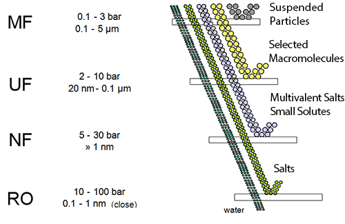
Reverse Osmosis (RO) is a membrane-based demineralization technique used to separate dissolved solids, such as ions, from solution (most applications involve water-based solutions, which is the focus of this work). Reverse Osmosis Membranes in general act as perm-selective barriers, barriers that allow some species (such as water) to selectively permeate through them while selectively retaining other dissolved species (such as ions). Figure 1.1 shows how RO perm-selectivity compares to many other membrane-based and conventional filtration techniques. As shown in the figure, RO offers the finest filtration currently available, rejecting most dissolved solids as well as suspended solids. (Note that although RO membranes will remove suspended solids, these solids, if present in RO feed water, will collect on the membrane surface and foul the membrane.
Osmosis
Osmosis is the process where water flows through a semipermeable membrane from a solution with a low concentration of dissolved
solids to a solution with a high concentration of dissolved solids.
Picture a cell divided into 2 compartments by a semipermeable membrane, as shown in Figure 1.2. This membrane allows water and some ions to pass through it, but is impermeable to most dissolved solids. One compartment in the cell has a solution with a high concentration of dissolved solids while the other compartment has a solution with a low concentration of dissolved solids. Osmosis is the natural process where water will flow from the compartment with the low concentration of dissolved solids to the compartment with the high concentration of dissolved solids. Water will continue to flow through the membrane until the concentration is equalized on both sides of the membrane.
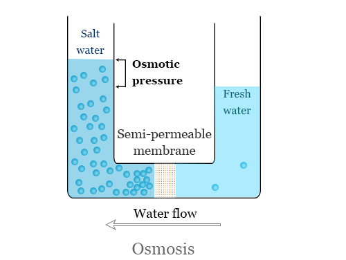
At equilibrium, the concentration of dissolved solids is the same in both compartments (Figure 1.2); there is no more net flow from one compartment to the other. However, the compartment that once contained the higher concentration solution now has a higher water level than the other compartment.
The difference in height between the 2 compartments corresponds to the osmotic pressure of the solution that is now at equilibrium.
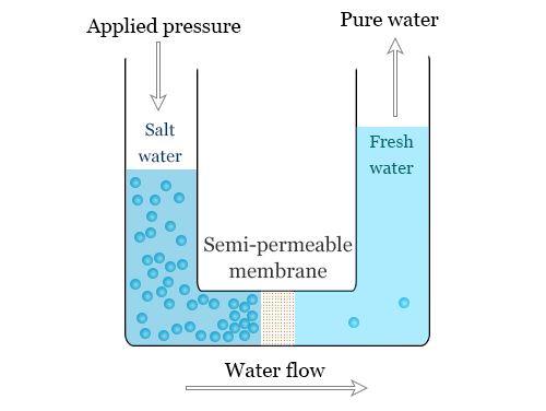
Reverse Osmosis
Reverse Osmosis is the process of Osmosis in reverse. Whereas Osmosis occurs naturally without energy required, to reverse the process of osmosis you need to apply energy to the more saline solution. A reverse osmosis membrane is a semi-permeable membrane that allows the passage of water molecules but not the majority of dissolved salts, organics, bacteria and pyrogens. However, you need to ‘push’ the water through the reverse osmosis membrane by applying pressure that is greater than the naturally occurring osmotic pressure in order to desalinate (demineralize or deionize) water in the process, allowing pure water through while holding back a majority of contaminants.
How Does Reverse Osmosis Work?
Reverse osmosis is a water treatment technology with continuous operation that uses pressure to pass source water through membrane, it is tin and thereby separate impurities from water.
Reverse Osmosis (RO) works by reversing the principle of osmosis, the natural tendency of water with dissolved salts to flow through a membrane from lower to higher salt concentration. This process is found throughout nature. Plants use it to absorb water and nutrients from the soil. In humans and other animals, kidneys use osmosis to absorb water from the blood.
The reverse osmosis principle reverses that process. In a RO system, pressure — usually from a pump— is used to overcome natural osmotic pressure, forcing feedwater with its load of dissolved salts and other impurities through a highly sophisticated, semipermeable membrane that removes a high percentage of the impurities. The product of this process is highly purified water.
The rejected salts and impurities concentrate and collect above the membrane and are passed from the system to drain or on to other processes. So, in a typical commercial or industrial application, 75% of the feedwater is purified. In applications in which water conservation is important, 85% of the feedwater is purified water.
An RO system uses cross-filtration, where the solution crosses the filter with two outlets: the filtered water goes one way and the contaminated water goes another way. So, to avoid the buildup of contaminants, cross-flow filtration allows water to sweep away contaminant buildup and enough turbulence to keep the membrane’s surface clean.
What Contaminants Does Reverse Osmosis (RO) Remove?
- Reverse Osmosis Systems have a very high effectiveness in removing protozoa (for example, Cryptosporidium, Giardia);
- RO Systems have a very high effectiveness in removing bacteria (for example, Campylobacter, Salmonella, Shigella, E. coli);
- Reverse Osmosis Systems have a very high effectiveness in removing viruses (for example, Enteric, Hepatitis A, Norovirus, Rotavirus);
- Osmosis Systems will remove common chemical contaminants (metal ions, aqueous salts), including sodium, chloride, copper, chromium, and lead; may reduce arsenic, fluoride, radium, sulfate, calcium, magnesium, potassium, nitrate, and phosphorous.
Performance and Design Calculations for Reverse Osmosis (RO) Systems
When we design a reverse osmosis system first, we have to know water source, water analysis report and application. Because these three challenges are important to choose material, applying pressure and flow. Meanwhile, after getting this information, in order to accurately measure the performance of an RO system water treatment you need the following operation parameters at a minimum for water supply:
- Feed pressure
- Permeate pressure
- Concentrate pressure
- Feed conductivity
- Permeate conductivity
- Feed flow
- Permeate flow
- Temperature
Recovery
Recovery (sometime referred to as “conversion”) is a term used to describe what volume percentage of influent water is “recovered” as permeate. Generally, RO system recoveries range from about 50% to 85%, with the majority of systems designed for 75% recovery. (Individual spiral wound membrane module recoveries vary from about 10% to 15%. A system recovery of 75% means that for every 100 gpm influent, 75 gpm will become permeate as reverse osmosis water and 25 gpm will be retained as concentrate, it is concentrated solution.
Recovery is calculated using the following equation:
% Recovery = (permeate flow / feed flow) * 100
At 75% recovery, the concentrate volume is one-fourth that of the influent volume. If it were assumed that the membrane retains all the dissolved solids, they would be contained in one-fourth of the volume of influent water. Hence, the concentration of retained dissolved solids would be four times that of the influent stream (since not all dissolved solids are retained by the membrane, this becomes only an approximation). This is called the “concentration factor.” At 50% recovery, the concentrate volume would be one-half that of the influent water. In this case, the dissolved solids would be concentrated by a factor of two, so the concentration factor would be 2. Table shows the concentration factor as a function of recovery. Understanding the reject concentration is important as the concentrate side of the membrane is the area where fouling and scaling occur accordingly.
Rejection
Rejection is a term used to describe what percentage of an influent species a membrane retains. For example, 98% rejection of silica means that the membrane will retain 98% of the influent silica. It also means that 2% of influent silica will pass through the membrane into the permeate (known as “salt passage”).
Rejection of a given species is calculated using the following equation:
% Rejection = [(Cf – Cp)/ Cf] * 100
Cf = influent concentration of a specific component
Cp = permeate concentration of a specific component
Salt Passage %
This is simply the inverse of salt rejection described in the previous equation. So, this is the number of salts expressed as a percentage that are passing through the RO system. So, the lower the salt passage, the better the system is performing. A high salt passage can mean that the membranes require cleaning or replacement.
Salt Passage % = (1 – Salt Rejection %)
Flux
Flux is defined as the volumetric flow rate of a fluid through a given area. In the case of RO, the fluid is water and the area is that of the membrane. In the language of RO, flux is expressed as gallons of water per square foot of membrane area per day, (gfd). So, the flux of water through an RO membrane is proportional to the net pressure driving force applied to the water.
J=K(ΔP-ΔΠ)
where:
J = water flux
K = water transport coefficient = permeability / thickness of the membrane active layer
ΔP = pressure difference across the membrane
ΔΠ = osmotic pressure difference across the membrane
Concentration Polarization
In simplest terms, the flow of water past an RO membrane is similar to that of the flow of water through a pipe, Figure 1.4. So, the flow in the bulk solution is convective, while the flow in the boundary layer is diffusive and is perpendicular to the convective flow of the bulk solution. There is no convective flow in the boundary layer accordingly.
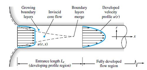
So, the slower the velocity of water through the pipe, the thicker the boundary layer becomes. Now, consider flow along the surface of a membrane. The same boundary layer forms as with flow through a pipe. However, with a membrane system, because there is a net flow out through the membrane, there is convective flow to the membrane, but only diffusional flow away from the membrane. Since diffusion is lower than convection, solutes rejected by the membrane tend to build up on the surface and in the boundary layer. Thus, the concentration of solutes at the membrane surface is higher than in the bulk solution.
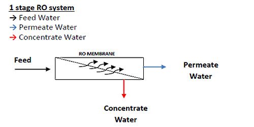
Reverse Osmosis (RO) System: Understanding the Difference Between Passes and Stages in a Reverse Osmosis (RO) System
The terms stage and pass are often mistaken for the same thing in an RO system and can be confusing terminology for an RO operator. It is important to understand the difference between a 1 and 2 stage RO and a 1 and 2 pass RO.
Arrays
Focusing on spiral wound membrane modules as the most common type of membrane modules used in industry today, an RO array or “skid” or “train” consists of a number of pressure vessels arranged in specific patterns. Figure 1.6 shows an array of 3 pressure vessels accordingly.
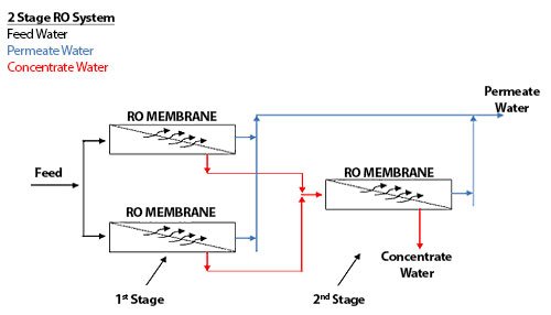
The pressure vessels are arranged into 2 sets, with 2 pressure vessels in parallel followed by 1 single pressure vessel. The 2 sets of pressure vessels are in series. Each set of pressure vessels in parallel (even if there is only 1 vessel) is called a STAGE.
The RO system shown in Figure 1.6 is called a 2-stage array, or a 2:1 array, indicating that there are 2 stages (by the 2 numbers), and the first stage has 2 pressure vessels, and the second stage has 1 pressure vessel. A 10:5 array would have 2 stages; the first stage would have 10 pressure vessels while the second stage would have 5 pressure vessels. A 4:2:1 array would have 3 stages, with 4 pressure vessels in the first stage, 2 pressure vessels in the second stage, and 1 pressure vessel in the third stage.
Recycle
Figure 5.6 shows an RO array with concentrate recycle. A concentrate recycle is generally used in smaller RO systems, where the cross-flow velocity is not high enough to maintain good scouring of the membrane surface. The return of part of the concentrate to the feed increases the cross-flow velocity and reduces individual module recovery, thereby reducing the risk of fouling.
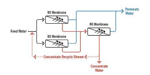
Recycle has some disadvantages as well:
- Lower overall product quality. This is because relatively high-concentration reject is added to the lower-concentration influent.
- Larger feed-pump requirements, because the RO feed pump must now pressurize both the influent stream plus the recycled reject stream. As a result, the RO feed pump must be larger, which may mean higher capital for the RO system.
- Higher energy consumption, again because of the reject and influent streams coming together and must be repressurized. This results in higher operating costs for the system.
Double Pass
Double pass (or two-pass) refers to further purification of permeate from one RO by running it through another RO. The first RO, as described in Chapter 5.1, would be the first pass. Permeate from the first pass is then sent to another RO known as the second-pass RO. The second-pass RO “polishes” the first-pass RO product to yield higher-quality water.
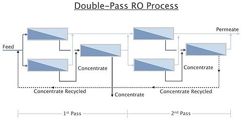
Figure 1.8 shows a double-pass RO system. The design principles for the second pass are generally the same as for the first pass. However, because of the low concentration of dissolved and suspended solids in the influent to the second pass, the influent and concentrate flows can by higher and lower, respectively, than for the first-pass RO system.
Pre-Treatment for Reverse Osmosis
The performance and successful operation of an RO system depends directly on the quality of water feeding the RO. The nature of feed water constituents can influence membrane performance by causing scaling, fouling, or degradation of the membrane.
Water quality is important before sending water to semi permeable RO membranes, pre-treatment effective to reduce membrane fouling, scaling, or degradation problem.
Suspended Solids
Suspended solids are typically measured using turbidity. Turbidity measures the light-scattering ability of particles in water. The water quality guidelines call for an influent turbidity of less than 1 Nephelometric Turbidity Units (NTU), which also happens to be a warranty requirement of membrane manufacturers. Exceed 1 NTU and the membrane warranty is voided. The lower the turbidity, the less likely the membranes are to foul with suspended solids. RO best practices call for feed water turbidity less than 0.5 NTU.
Microbes
Microbial fouling of RO membranes is a significant issue. Bacterial colonies will grow virtually anywhere in the membrane module where the conditions are favorable. Concentration polarization provides an environment next to the membrane surface that is enriched in nutrients for microbes. Satellite colonies can break off and begin to grow elsewhere within the membrane module, increasing the surface area of membrane that is covered with microbes and their associated biofilm. Microbial fouling will lower membrane productivity, increase operating pressure, and increase pressure drop.
Organics
Organics adsorb to the membrane surface resulting in flux loss that can be permanent in some cases.4 Adsorption is favored at pH less than 9 and where the organic compounds are positively charged. Particularly troublesome are emulsified organics, which can form an organic film on the membrane surface. Organic fouling exacerbates microbial fouling, as many organics are nutrients for microbes. It is recommended that the organic concentration, as measured by total organic carbon (TOC) be less than 3 ppm to minimize fouling potential. Organic fouling of the membrane will decrease productivity of the membrane.
Color
Color also adsorbs onto the surface of the RO membrane. Color is typically made up of naturally occurring humic substances that form when organic substances such as leaves decay. Humic substances are themselves composed of three different types of organic compounds. Humic acid is that color which precipitates during acidification; these organics are dark brown to black in color. Fulvic acid does not precipitate during acidification; these substances are yellow to yellow-brown in color. Finally, humin is not soluble at any pH and is black in color.
Metals
RO membranes will readily foul with precipitated metals, including iron, manganese, and aluminum. Soluble iron and manganese (and cobalt present in some bisulfite solutions used for dechlorination) are also a problem for RO membranes. These metals will catalyze the oxidation of the RO membrane resulting a degradation to the membrane. By dropping the pH and reducing the oxygen concentration, higher concentrations of soluble iron can be tolerated. Metal fouling will increase pressure drop and decrease productivity. Oxidization of the membrane with soluble metals will result in lower salt rejection and higher productivity.
Hydrogen Sulfide
Hydrogen sulfide is typically found in well water that is devoid of oxygen. This compound easily oxidizes and releases elemental sulfur, which is very sticky and results in irreversible fouling of RO membranes. Metal sulfides can also form, which can precipitate. Deposits can be sooty-black or a pasty-gray. Fouling with elemental sulfur or metallic sulfides will cause a decrease if flux and an increase in salt passage.
Silica
Silica, as insoluble silicates and as soluble or “reactive” silica, can cause problems for an RO system. Insoluble silicates form when silica precipitates. When iron and aluminum are present, silicates of these metals can form quickly and at silica concentration less then saturation. Saturation of soluble silica is a function of temperature and pH. Silica is more soluble at higher temperature and at pH below 7.0 and above 7.8.
Soluble silica often limits the recovery of an RO system because of the potential for scaling and the difficulty in removing silica scale from membranes. Silica antiscalants that can handle up to about 200 ppm silica (depending on the conditions and antiscalant manufacturer) are available.
Calcium Carbonate
Calcium carbonate scaling is perhaps the most common type of problem, with the possible exception of microbial fouling, that RO membranes experience. Fortunately, it is fairly easy to detect and handle. Basically, if the ion product (IP) of calcium carbonate in the RO reject is greater than the solubility constant (Ksp) under reject conditions, then calcium carbonate scale will form. If IP < Ksp, scaling in unlikely.
Trace Metals-Barium and Strontium
Barium and strontium form sulfate scales that are not readily soluble. In fact, barium is the least soluble of all the alkaline-earth sulfates. It can act as a catalyst for strontium and calcium sulfates scale. Analyses of the ion product with the solubility constants for barium and strontium sulfates is necessary to determine the potential for scaling with these species. If the ion product (IP) for barium sulfate exceeds the solubility constant, scale will form. Note that in the case of strontium sulfate, if IP > 0.8Ksp scaling is likely. However, the induction period (the time it takes for scale to form) is longer for these sulfate-based scales than it is for calcium carbonate scale.
Barium and strontium can be reduced in RO feed water using sodium softening. Antiscalant can be used to control or inhibit scaling without reducing the concentration of either species.
Chlorine
Polyamide, composite membranes are very sensitive to free chlorine (recall from Chapter 4.2.1 that cellulose acetate membranes can tolerate up to 1 ppm free chlorine continuously). Degradation of the polyamide composite membrane occurs almost immediately upon exposure and can result in significant reduction in rejection after 200 and 1,000-ppm hours of exposure to free chlorine (in other words after 200-1,000 hours exposure to 1 ppm free chlorine). The rate of degradation depends on two important factors:
1) degradation is more rapid at high pH than at neutral or low pH,
2) the presence of transition metals such as iron, will catalyze the oxidation of the membrane.
The mechanism of degradation is the loss of polymer crosslinking. This results in the membrane polymer dissolving, similar to a nylon stocking when exposed to chlorine bleach. Damage is irreversible and will continue as long as the membrane is exposed to the oxidizer.
Pretreatment Solutions
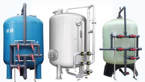
Multimedia Pressure Filters
Multimedia pressure filters are designed to reduce turbidity and colloids (measured as SDI) in water. These filters can remove particles
down to about 10 microns in size. If a coagulant is added to the filter influent stream, reduction of particles down to 1-2 microns can
sometimes be accomplished. Typical removal efficiency for multimedia pressure filters is about 50% of particles in the 10 – 15 micron size
range. Influent turbidity for RO pretreatment is limited to about 10 NTU. At turbidity greater than 10 NTU, these filters may backwash too frequently to provide consistent effluent quality at reasonable run lengths.
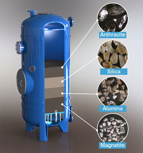
Multimedia pressure filters contain graduated layers of anthracite on top of sand on top of garnet. Figure 1.9 shows a cross section of a multimedia filter. The fine garnet material is denser than the coarse anthracite material. There is no discrete boundary between each of the layers; there is a gradual transition from one material density and coarseness to the next. Otherwise, there would be a buildup of particles at each interface. Particles are subsequently removed through the filter using physical entrapment. Larger particles are removed on top through the anthracite, while smaller particles are subsequently removed through the sand and garnet. Multimedia filters offer finer filtration than dual media (anthracite and sand) filters due to the relatively fine nature of the garnet.
Carbon Filters
Activated carbon filters are used to reduce the concentration of organics in RO feed water. These filters are also used to remove oxidants such as free chlorine from RO feed water.
Activated carbon is derived from natural materials such as bituminous coal, lignite, wood, fruit pits, bones, and coconut shells, to name a few. The raw materials are fired in a low oxygen environment to create char, which is then activated by steam, carbon dioxide or oxygen. For most industrial applications, bituminous carbon is used. This is because of the smaller pores size, higher surface area and higher density than other forms of carbon giving bituminous carbon higher capacity for chlorine. Carbon can also come in one of 3 forms: powdered (PAC), extruded block (CB), and granular (GAC).
Most industrial applications used GAC as this is the lowest cost of the 3 types of carbon media and this type of carbon can be reused.
All carbon is characterized by high surface area. A gram of carbon can have surface area in excess of 500m2, with 1,500 m2 being achievable. High surface area is necessary for reduction of organics and chlorine within reasonable residence time.
Iron Filters
Many well waters contain soluble iron, manganese, and hydrogen sulfide that oxidize in the presence of oxygen or chlorine to form insoluble hydroxides and elemental sulfur, all of which foul RO membranes (in the case of elemental sulfur, the fouling is irreversible).
Manganese dioxide media is used to oxidize and filter out the oxidized metals. Specifically, manganese greensand and alternatives such as BIRM (sometimes called better iron removal media) and Filox, are three types of media containing manganese dioxide that are used to oxidize and filter iron, manganese and the like (BIRM is a registered trademark of Clack Corporation, Windsor, Wisconsin). Filox contains the most manganese dioxide and has the longest life expectancy of the three media.
Sodium Softeners
Sodium softeners are used to treated RO influent water to remove soluble hardness (calcium, magnesium, barium, and strontium) that can form scale on RO membranes. Once known as sodium zeolite softeners, zeolites have been replaced with synthetic plastic resin beads. For sodium softeners, these resin beads are strongly acidic cation (SAC) polystyrene resin in the sodium form. The active group is benzene sulfonic acid, in the sodium, not free acid form.
Spent Resin Filters
Spent or exhausted resin has been used on occasion to filter RO influent water. These filters are designed to remove silt and reduce SDI from surface water sources.
Ultraviolet Irradiation
Ultraviolet (UV) irradiation is used to destroy bacteria and reduce organic compounds (measured as TOC) as well as destruction of chlorine and chloramines. This technique involves passing water over a UV lamp that is operating at a specific wavelength of energy.
Bacteria require a dosage of radiation equivalent to about 10,000 – 30,000 microwatt-seconds/square centimeter. This can achieved by using a 254-nanometer wavelength. This wavelength alters the DNA of microbes, causing them to be unable to reproduce, leading to their death.
Chemical Pretreatment
Chemical pretreatment focuses on bacteria, hardness scale, and oxidizing agents. Chemicals are used to remove, destroy, inhibit, or chemically reduce these species.
Chemical Oxidizers for Disinfection of Reverse Osmosis Systems
Chemical oxidizers used to disinfect RO systems include hydrogen peroxide (peroxide), halogens, and ozone. Although halogens (and specifically chlorine) are the most popular oxidizers using in conjunction with RO pretreatment, they do not have the highest oxidization-reduction potential (ORP). As the table shows, ozone and peroxide have nearly twice the ORP or disinfection capability as chlorine.
Despite the relatively low OW, chlorine is the most commonly used disinfectant in brackish water RO pretreatment due to its ease of use and its ability to provide residual disinfection (for seawater desalination using RO, bromine (as HOBr) is predominantly used because the high bromine concentration in typical seawater would rapidly form hypobromous acid if hypochlrous acid were used).
Antiscalants
Sequestering agents (also known as scale inhibitors or antiscalants) are used to minimize the potential for forming scale on the surface of an RO membrane. Antiscalants work by one of three methods:
- Threshold inhibition-the ability to keep supersaturated salts in solution
- Crystal modification-the ability to change crystal shapes, resulting in soft, non-adherent scales
- Dispersion-the ability to impart a highly negative charge to the crystal thereby keeping them separated and preventing propagation.
Anti-Fouling
Fouling occurs when contaminants accumulate on the membrane surface effectively plugging the membrane. There are many contaminants in municipal feed water that are naked to the human eye and harmless for human consumption, but large enough to quickly foul (or plug) an RO system. Fouling typically occurs in the front end of an RO system and results in a higher pressure drop across the RO system and a lower permeate flow. This translates into higher operating costs and eventually the need to clean or replace the RO membranes. Fouling will take place eventually to some extent given the extremely fine pore size of an RO membrane no matter how effective your pretreatment and cleaning schedule is. However, by having proper pretreatment in place, you will minimize the need to address fouling related problems on a regular basis at treated water.
Fouling can be caused by the following:
- Particulate or colloidal mater (dirt, silt, clay, etc.)
- Organics (humic/fulvic acids, etc)
- Microorganisms (bacteria, etc). Bacteria present one of the most common fouling problems since RO membranes in use today cannot tolerate a disinfectant such as chlorine and therefore microorganisms are often able to thrive and multiply on the membrane surface. They may produce biofilms that cover the membrane surface and result in heavy fouling.
- Breakthrough of filter media upstream of the RO unit. GAC carbon beds and softener beds may develop an under drain leak and if there is not adequate post filtration in place the media can foul the RO system.
Sodium Metabisulfite
Dechlorination of feed water to polyamide composite membranes is necessary as a polyamide membrane polymer cannot tolerate oxidizers of any kind. The options for dechlorination include activated carbon, sodium metabisulfite chemical feed, and UV radiation. Carbon has its own set of difficulties, as described previously, and UV radiation can be capital intensive. Sodium metabisulfite is the most commonly used technique to dechlorinate RO influent.
Reverse Osmosis Skids
An RO skid includes the pressure vessels in which the membrane modules are contained. Skids also commonly include cartridge filters in a housing or housings and an RO feed pump, although combinations exist with just pressure vessels or pressure vessels with cartridge filters. Finally, there are included on the skid instrumentation and controls for the system. Figure shows an RO skid with these components.
Figure shows a detailed process flow diagram (PFD) for a 2:1 array RO system. The figure shows the major components of an RO system including instrumentation, control switches, and valves.
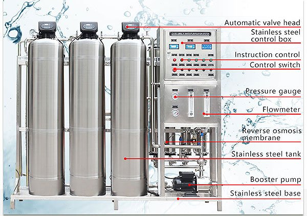
Components of an RO system discussed in this chapter include:
- Cartridge filters
- RO feed (booster) pumps
- Pressure vessels
- Manifolding-materials of construction
- Instrumentation
- Controls
- Data acquisition and management
- RO skid frame
- Auxiliary equipment
Cartridge Filters
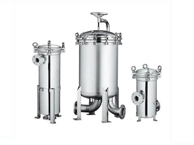
Cartridge filters are usually used to directly pretreat influent water just prior to the RO membranes. Cartridge filters are designed to prevent resin and media that may have carried over from upstream softeners and filters, from reaching the RO feed pump and damaging the impeller as well as reaching the RO membrane modules and blocking off the feed channels. They are also designed to remove macroparticles that could physically abrade or penetrate the thin membrane layer. Cartridge filters are not intended for bulk removal of suspended solids, turbidity, or SDI.
Reverse Osmosis Feed Pumps
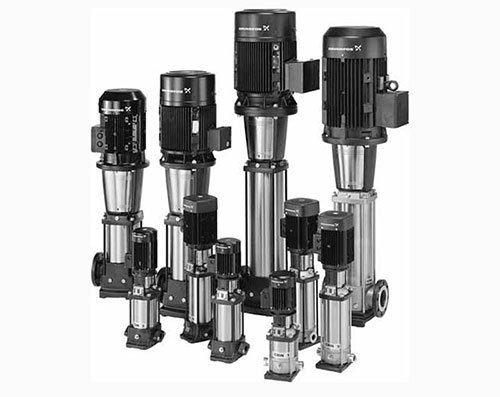
The most common type of industrial, brackish-water, RO feed pump (sometimes referred to as the “booster” pump) is a centrifugal pump, although some older units still use positive displacement pumps. Centrifugal pumps are well suited to brackish water Reverse Osmosis Filter applications because these pumps operate favorably at medium flows (typically less than 1,000 gpm) at relatively low pressures (up to 400 psig). Positive displacement pumps have higher hydraulic efficiencies but are plagued with higher maintenance requirements relative to centrifugal pumps.
Pressure Vessels
A pressure vessel is the pressure housing for the membrane modules and contains the pressurized feed water. Various pressure ratings are available depending on the application:
- Water softening:50 psig up to 150 psig
- Brackish water reverse osmosis: 300 psig up to 600 psig
- Seawater reverse osmosis: 1,000 psig up to 1,500 psig
Pressure vessels are made to specifically to accommodate whatever diameter of membrane module being used, be it a 2.5-inch diameter tap water membrane module up to 18-inch diameter industrial membrane module. The length of the pressure vessel can be as short a one membrane module in length up to seven membrane modules in series.
Manifolding-Materials of Construction
The low pressure piping on an RO skid is typically schedule 80 PVC. This includes the feed, low-pressure concentrate, and product piping. High pressure piping is typically schedule 10,316L stainless steel (suitable for waters with concentrate streams below 7,000 ppm TDS). Sanitary applications (such as food, pharmaceutical, or biotechnical processing) are generally all stainless to allow for disinfection of the system.
RO permeate distribution piping considerations need to be mindful of the fact that the permeate is highly corrosive. Retrofitting an RO system into a facility with carbon steel permeate piping is difficult, as the piping will corrode. Nonmetallic materials such as plastics and fiberglass are recommended for low-pressure RO product distribution piping.
Instrumentation
Instrumentation is key to operating and monitoring an RO system. Unfortunately, there is little uniformity among RO equipment vendors in the instrumentation they provide.
Most vendors do supply the influent, reject, and permeate instrumentation listed with the exception of the pH, temperature, and chlorine or ORP monitors, which are sometimes available as options. However, many vendors do not include the interstage instrumentation. This is an important omission, as this instrumentation is vital to determining whether problems with an RO system are due to fouling in the first stage of an RO or scaling in the last stage of an RO.
Controls
Most RO skids are equipped with either a microprocessor or programmable logic controller (PLC). Both the microprocessor and the PLC replaced mechanical relay panels, that were very large in size, and had tendencies for difficult troubleshooting. From the early time of RO manufacturing, control panels in most cases were large enough for the average-sized human to stand in. Today’s technology allows for controls to be mounted directly to the RO units, and save a great deal of space. The PLC and microprocessor offer digital relay technology that are connected within a base moduals, other wise known as bricks (or chipsets). This is opposed to the electromechanical relay.
Microprocessors are usually found on smaller or lower-priced RO systems, while PLC controls are used for larger, more complicated systems that require greater control over process conditions.Major suppliers of PLC units for RO systems include Allen-Bradley, and Siemens.
Data Acquisition and Management
An operator interface is used to record data gathered by the PLC The operator interface is usually another computer (sometime called the human-machine interface or HMI). The HMI uses process displays with real-time sensor readings so that the operator can quickly assess the status of the system. The operator uses the control panel to adjust alarm settings and to turn on and off process equipment. Once running, however, the PLC controls and runs the system automatically, without further input from the operator. Common HMI status indicators are listed below:
- All shutdown alarms
- Total run time
- RO operating mode
- Recovery
- Influentflow
- Reject flow
- Permeate flow
- Pumpstatus
- Valve status
Reverse Osmosis Skid Frame
Reverse osmosis skids are typically contained within a frame of stainless steel 304, galvanized or urethane-coated steel. Skids should be designed for easy access for monitoring and maintenance. Access to controls, instruments, valves, the pump and motor, and membranes is essential. Access to the permeate from each pressure vessel is often overlooked. Without such access, profiling and probing used to troubleshoot poor performance is not possible.
Clean-in-Place CIP System

RO membranes will inevitably require periodic cleaning, anywhere from 1 to 4 times a year depending on the feed water quality. As a general rule, if the normalized pressure drop or the normalized salt passage has increased by 15%, then it is time to clean the RO membranes. CIP system makes this cleaning job automatically or manual in water filtration process.